


Rosemount 3144P Temperature Transmitter
Master installation, parameter setup with Hart 475, and troubleshooting for industry-leading temperature measurement accuracy
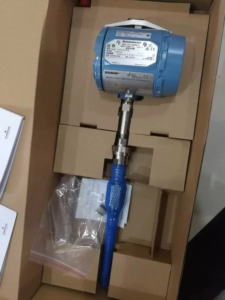
The Rosemount 3144P Temperature Transmitter represents the gold standard in industrial temperature measurement, delivering exceptional accuracy, stability, and reliability for critical control and safety applications. With HART protocol support and dual-sensor input capability, this transmitter offers unmatched flexibility for complex process environments.
As a trusted supplier of genuine Rosemount instrumentation, we provide comprehensive technical support to ensure optimal performance of your 3144P transmitters in the field.
Key Features and Capabilities
Dual-Sensor Input Architecture
The 3144P supports both single and dual sensor configurations, enabling:
- Independent temperature measurements from two sensors
- Differential temperature calculations
- Temperature averaging for enhanced accuracy
- Redundant measurement for critical safety applications
Superior Accuracy
Industry-leading measurement precision for demanding process control
HART Protocol
Full HART 7 compatibility for seamless integration
Exceptional Stability
Long-term reliability minimizes calibration frequency
Step-by-Step Installation Procedure
⚠️ Critical Installation Note: Mount the transmitter at the highest point of the cable conduit to prevent moisture ingress into the transmitter housing.
Installation Steps
Mount the thermowell to the process vessel wall. Tighten securely and perform leak testing to ensure process integrity.
Install all necessary unions, connectors, and extension fittings. Use certified thread sealant on all threaded connections.
Thread the sensor into the thermowell or directly onto the process piping. Verify all sealing requirements are met.
Attach the transmitter to the thermowell or sensor assembly. Apply certified thread sealant to all threaded connections.
Install the field conduit into the transmitter conduit entry and route cables into the transmitter housing.
Pull field wiring leads to the terminal side of the housing.
Connect transmitter leads to the sensor terminals following the wiring diagram.
Install and tighten both transmitter covers to maintain environmental protection rating.
HART 475 Configuration Guide
The following procedures detail parameter configuration using the Emerson Hart 475 Field Communicator. These shortcut sequences accelerate field commissioning.
1. Basic Sensor Configuration
| Parameter | Description |
|---|---|
| Sensor 1 Type | Select RTD or thermocouple type (Pt100, Type K, Type J, etc.) |
| Sensor 1 Connection | Configure wiring configuration (2-wire, 3-wire, 4-wire) |
| Sensor 1 Units | Set temperature units (°C, °F, K, °R) |
| Damping | Configure damping time constant for signal smoothing |
2. Dual Sensor Channel Configuration
| Measurement Mode | Function |
|---|---|
| Sensor 1 Temperature | Use Channel 1 only |
| Sensor 2 Temperature | Use Channel 2 only |
| Differential Temperature | Calculate difference between two sensors |
| Average Temperature | Calculate average of both sensors |
| First Good Temperature | Automatic failover to backup sensor |
3. Alarm Configuration
Configure high and low alarm setpoints to trigger process alerts when temperature exceeds safe operating limits.
4. Loop Test and Simulation
Use loop testing to verify 4-20mA output signal integrity and validate control system integration before commissioning.
Troubleshooting Guide
🔧 Required Tools: Wrenches, Phillips screwdriver, multimeter, Hart 475 communicator, 725 calibrator, clean cloth
Common Fault Symptoms and Solutions
❌ Symptom 1: Reading Too High
Possible Causes:
- RTD wire break (indicates infinite resistance)
- Loose RTD wire connections
- Poor RTD wire contact
- RTD element failure
❌ Symptom 2: Reading Fluctuates
Possible Causes:
- Process condition changes
- Moisture in thermowell
- Transmitter hardware fault
- Intermittent wiring connections
❌ Symptom 3: Local Display vs Control Room Discrepancy
Possible Causes:
- Transmitter malfunction
- Signal cable insulation damage causing current leakage
- Mismatched range settings between field and control room
- Ground loop issues
Systematic Troubleshooting Procedure
✅ Step-by-Step Resolution Process
- Safety First: Consult with process operators about interlock status. Verify the control loop can be safely taken out of service.
- Process Review: Check if recent process changes could explain temperature variations before assuming instrument fault.
- Visual Inspection: Remove transmitter covers carefully (protect threads). Inspect wiring connections for looseness or corrosion.
- Resistance Check: Use multimeter to measure RTD resistance. Convert to temperature and compare with control room reading.
- Element Replacement: If resistance reads infinite, the RTD element is likely broken and requires replacement.
- Clean Components: Inspect for dirt or moisture in thermowell. Clean gently with cloth—avoid excessive force on RTD element.
- Parameter Verification: Use Hart 475 to check sensor type, units, damping, and linearization settings.
- Transmitter Test: Perform simulation test with Hart 475 or apply known resistance/current with 725 calibrator to verify transmitter response.
- Reassembly: Apply PTFE tape or 704 sealant to threads. Reinstall covers securely.
- Documentation: Record findings and return system to service.
Related Reading
- Rosemount 3051 Pressure Transmitter Selection Guide: Technical Specifications
- Temperature Transmitter Configuration and Application: A Complete Technical Guide
- Endress+Hauser iTHERM ModuLine TM131: Modular Industrial Temperature Sensor
- E+H Instrument Field Commissioning & Maintenance Guide
- Transmitter Zero Migration Guide: Positive vs Negative Migration Explained
- Fisher DVC6200 Positioner Vibration Failure: Case Study and Root Cause Analysis
Need Technical Support?
Our application engineers are available to assist with Rosemount 3144P configuration, troubleshooting, and application guidance.
Email: sales@yunrui-controls.com | WhatsApp: 18710784030