








Fisher DVC6200 HART Communication Fault
Terminal Block Diagnosis & Field Repair Guide
What Is an Intermittent HART Communication Fault?
An intermittent HART communication fault on a Fisher DVC6200 digital valve positioner is one of the most frustrating failures a process engineer can face. The symptoms are deceptively simple: the positioner stops responding to 4-20 mA commands from the DCS, the valve stays frozen at its last position, and the control loop goes into an uncontrolled state. Yet a quick power cycle restores everything to normal — no error codes, no permanent damage, no clear culprit.
This article walks through a real field case where a DVC6200 exhibited exactly this pattern. We cover the root cause analysis, the step-by-step diagnostic procedure using only a multimeter and basic hand tools, and the corrective action that eliminated the fault permanently. If you maintain control valves in critical service, this is a failure mode worth understanding.
⚠️ Field Warning: This fault is dangerous because it is silent. The valve does not move, there is no alarm, and the process drifts until an operator notices. If your DVC6200 has ever “fixed itself” after a power cycle, read on.
Fault Symptoms and Field Behavior
The fault described here occurred on a DVC6200 in continuous process service. The following pattern was observed over several weeks:
- 📡 Communication loss: HART communication dropped intermittently between the DCS and the positioner.
- 🔒 No valve response: Despite a valid 4-20 mA command signal from the control room, the valve position did not change.
- ⚠️ Accident state: The valve remained at its last position, causing process deviation and potential safety risk.
- 🔄 Power cycle recovery: Removing and reapplying power to the DVC6200 restored normal operation immediately.
- ✓ No persistent fault: After restart, the valve returned to the correct position dictated by the DCS output. No error codes were logged.
This is a classic self-healing communication fault — the kind that makes root cause analysis difficult because the evidence disappears after restart.
Manufacturer Analysis: Why Power Cycling Works
When this case was escalated to the manufacturer, the analysis focused on what a power cycle actually does. Restarting the DVC6200 reinitializes the internal logic, resets the HART modem, and re-establishes the communication handshake with the DCS. If the fault goes away after restart, the following are effectively ruled out:
- Loop resistance issues (would persist after restart)
- DCS I/O card failure (would affect other devices)
- HART communication interference (would recur under same conditions)
- Corrupted configuration parameters (would not self-correct)
The conclusion: the fault is almost certainly in the terminal box wiring — specifically, a loose or degraded electrical connection inside the DVC6200 housing that causes intermittent signal interruption. When the connection drops, the HART signal packets are lost, the input loop logic locks up, and the positioner stops responding to commands. Power cycling temporarily re-establishes the connection until the next vibration or thermal cycle breaks it again.
💡 Key Insight: Any fault that “fixes itself” with a restart points to a physical connection problem, not a software or configuration issue. Focus your diagnosis on wiring integrity.
Diagnostic Tools Required
Step-by-Step Diagnostic Procedure
Step 1: Remove the DVC6200 Cover
Before beginning any electrical test, isolate the loop power and ensure the area is safe for maintenance. Use a 6 mm hex key to remove the three cover retaining screws on the DVC6200 housing.
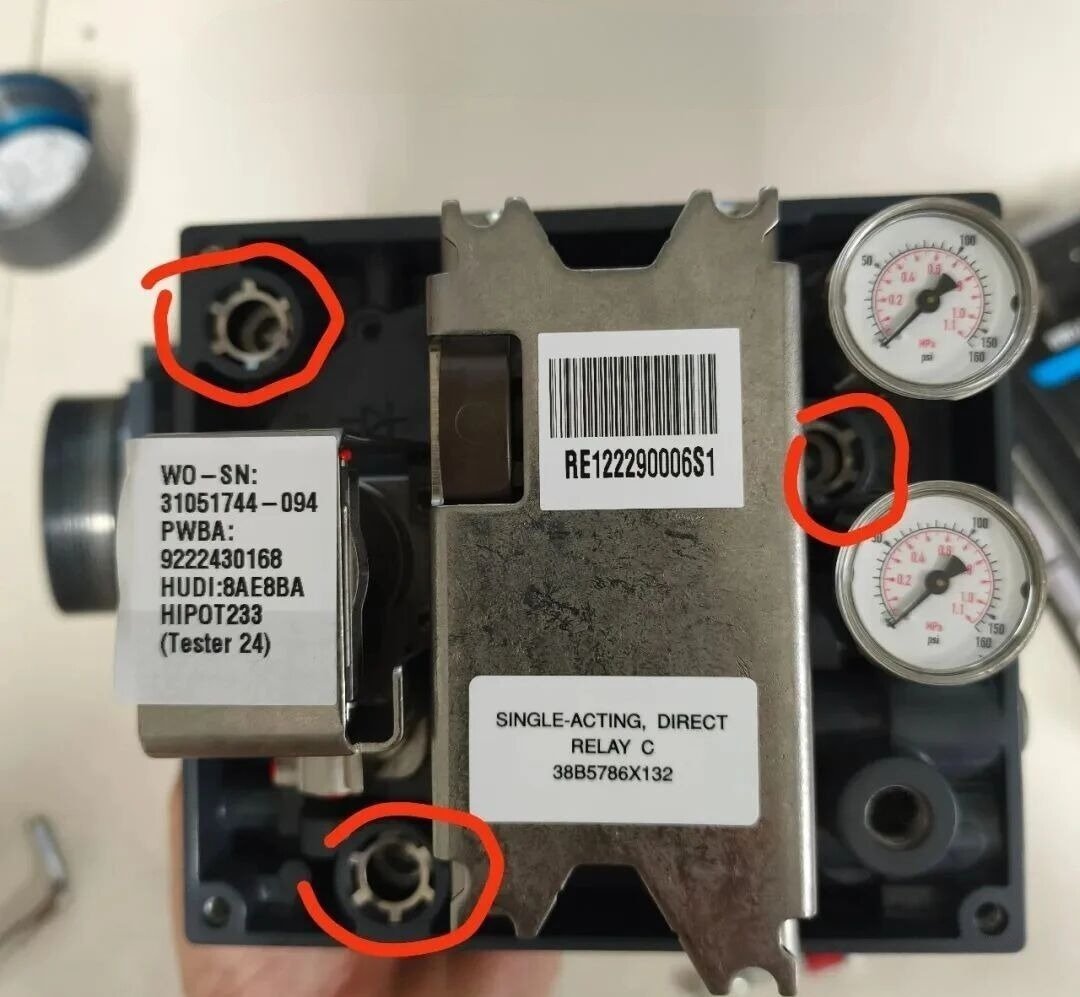
Lift the cover carefully to expose the terminal compartment. Take note of the wire routing and connector positions before disconnecting anything.
Step 2: Disconnect the Wire Harness
The DVC6200 terminal compartment contains color-coded wire connectors. Gently pull the red, black, and green wire plugs from the terminal block. These carry the loop power and HART signal.
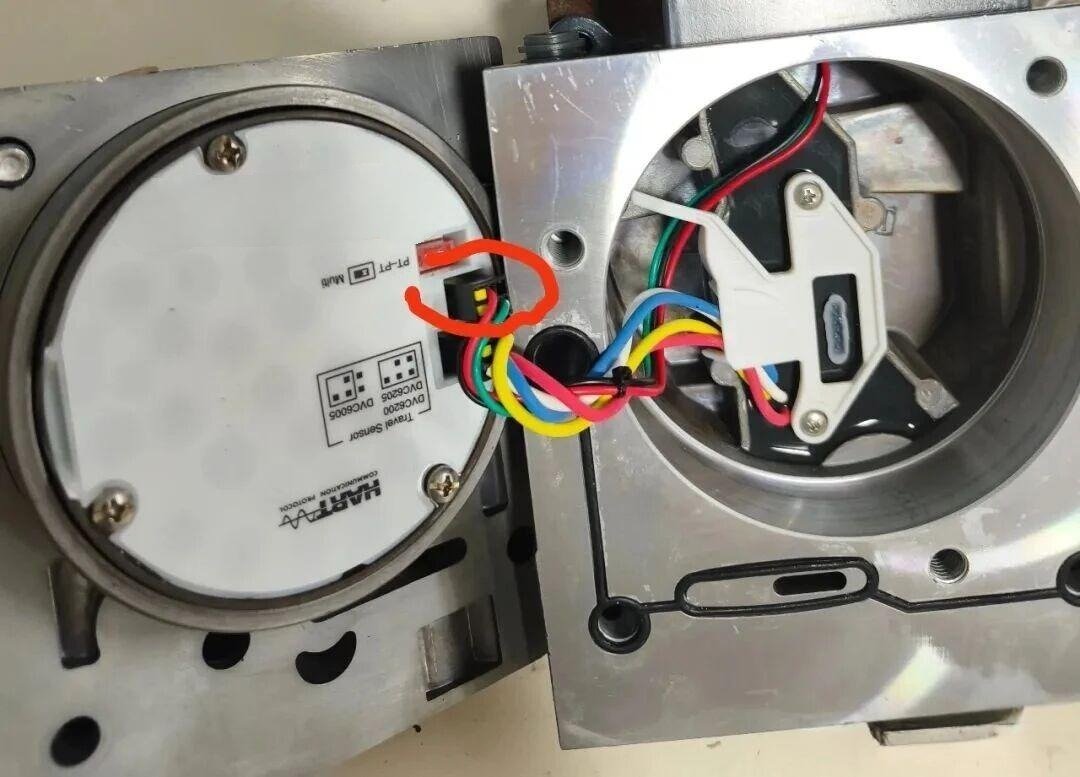
⚠️ Caution: Do not pull on the wires themselves. Grip the connector body to avoid damaging the crimp or insulation.
Step 3: Measure Red Wire (Loop+) Resistance
Remove the terminal block assembly from the circuit board to access the contact points. Set your multimeter to resistance (Ω) mode. Connect one probe to the red wire and the other to the Loop+ terminal. The resistance should be ≤ 1 Ω.
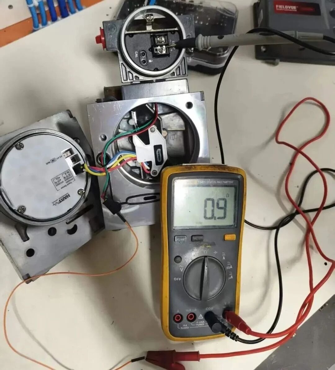
✓ Field reading: 0.9 Ω — within specification.
Step 4: Measure Black Wire (Loop-) Resistance
Repeat the measurement between the black wire and the Loop- terminal. Again, the expected value is ≤ 1 Ω.
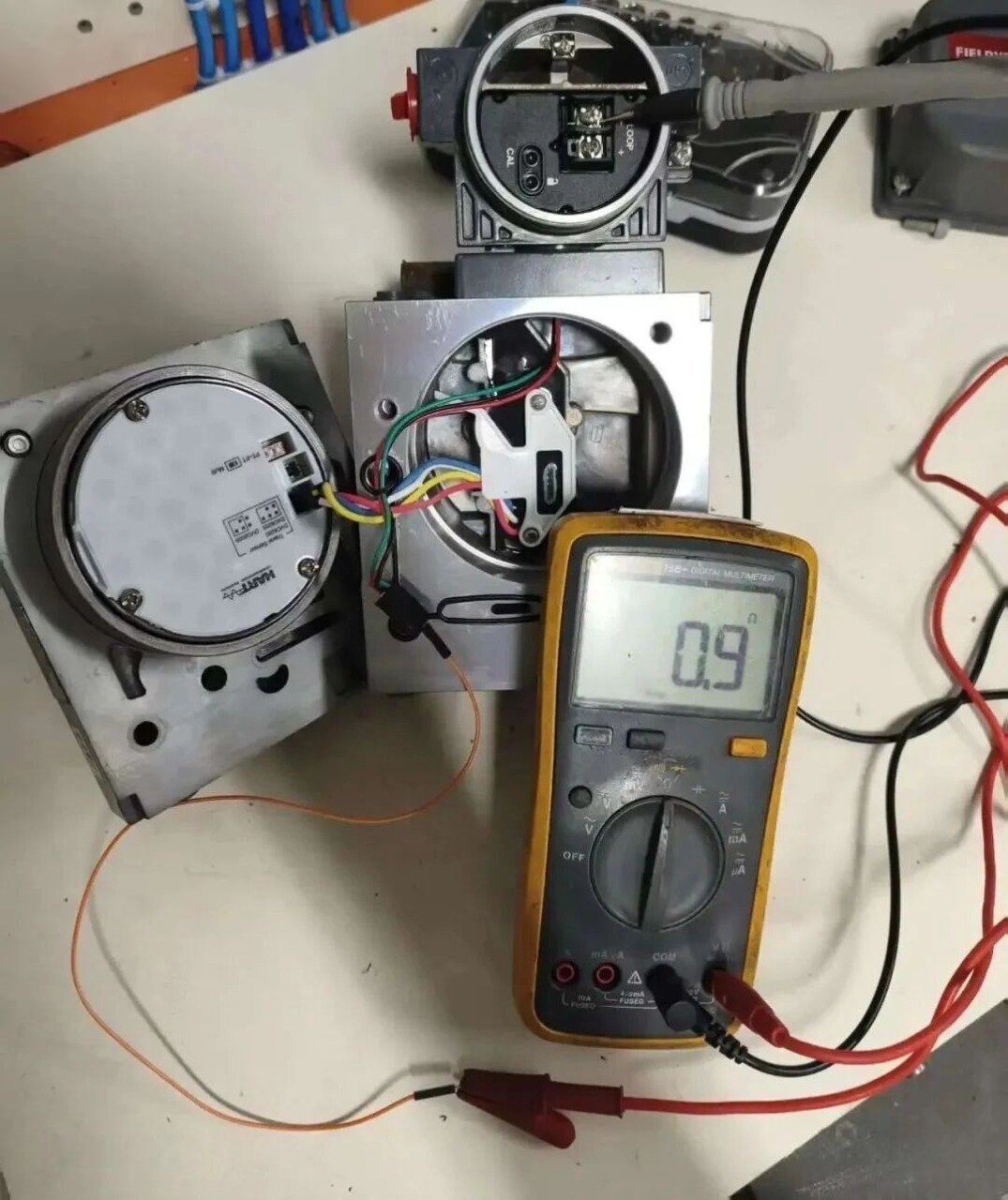
✓ Field reading: 0.9 Ω — within specification.
Step 5: Measure Loop+ to Loop- Resistance (Critical Test)
This is the critical test. Use a shorting wire to bridge the red and black wires together at the connector side. Then measure the resistance between Loop+ and Loop- at the terminal block. This tests the entire current path through the terminal assembly.
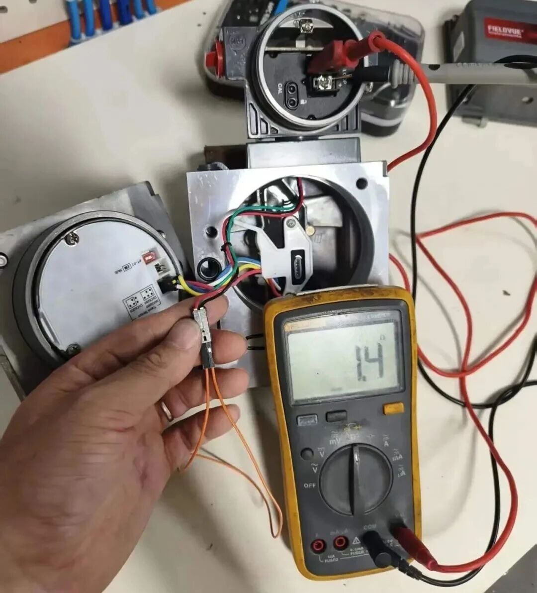
Expected value: ≤ 1 Ω
✗ Field reading: 1.4 Ω — ABOVE SPECIFICATION
🔍 Finding: A 1.4 Ω reading on the Loop+/Loop- path indicates degraded contact resistance inside the terminal block. This is sufficient to cause intermittent HART packet loss under vibration or thermal stress, explaining the communication dropouts.
Step 6: Measure Loop+ to Ground Resistance
Check for leakage or shorting to ground. Measure resistance between Loop+ and the equipment ground conductor.
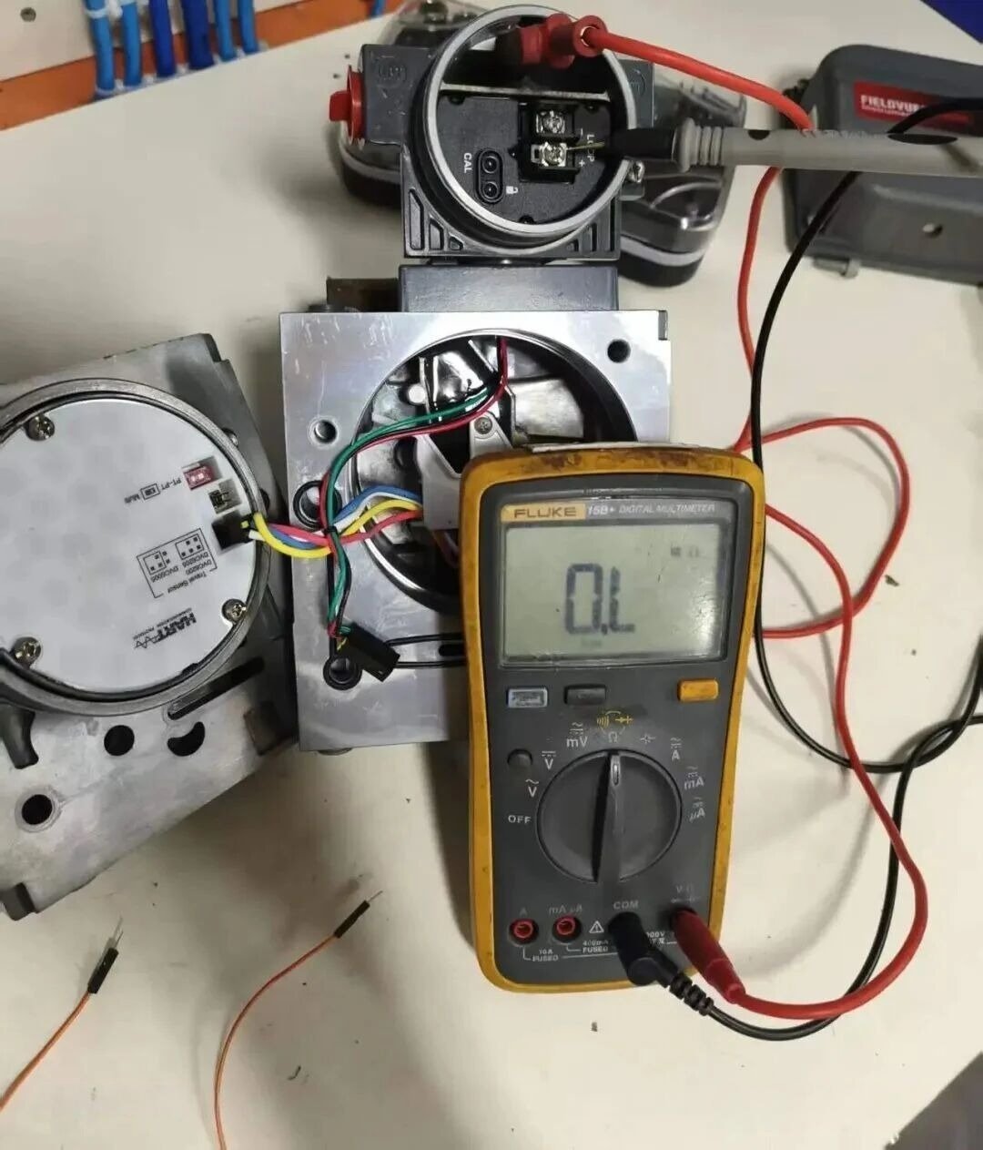
Expected value: Open circuit (infinite resistance)
✓ Field reading: Open — no ground fault detected.
Step 7: Measure Loop- to Ground Resistance
Repeat the insulation test for the Loop- conductor.
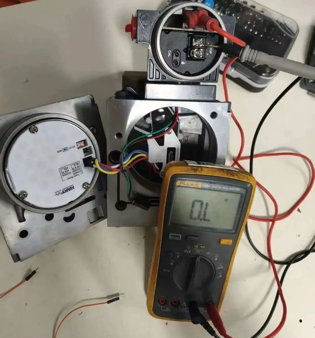
Expected value: Open circuit
✓ Field reading: Open — no ground fault detected.
Test Results Summary
Root Cause and Corrective Action
The elevated 1.4 Ω resistance on the Loop+/Loop- path through the terminal block is the smoking gun. In a 4-20 mA HART loop, even small increases in contact resistance can cause:
- 📉 HART signal attenuation or packet loss
- 📡 Intermittent communication dropouts under vibration
- 🔒 Input loop logic lockup when the signal falls below the detection threshold
- ❌ Complete loss of command response while the analog signal appears normal
The root cause is terminal block degradation — likely from moisture ingress, thermal cycling, or contact surface oxidation over time. The terminal block is a replaceable component in the DVC6200.
✅ Corrective Action: Replace the DVC6200 terminal block assembly. After replacement, repeat the Loop+/Loop- resistance test. The reading should drop to ≤ 1 Ω. This case was resolved permanently after terminal block replacement — no further communication dropouts were observed.
Preventive Recommendations
- 🔍 Inspect terminal compartments annually during scheduled maintenance. Look for corrosion, moisture, or discolored contacts.
- 🔒 Verify cover seal integrity. The DVC6200 cover gasket prevents moisture ingress. Replace if damaged or compressed.
- 📝 Document baseline resistance values during commissioning. Compare during future maintenance to detect degradation trends.
- 📦 Consider spare terminal blocks in your critical valve maintenance kit. They are inexpensive and can eliminate hours of troubleshooting.
FAQ
Why does the DVC6200 work after a power cycle if the terminal block is faulty?
Power cycling reinitializes the HART modem and input logic. If the contact resistance is borderline (as in this case, 1.4 Ω), the circuit may work temporarily until vibration or temperature changes push it over the threshold again.
Can I clean the terminal block instead of replacing it?
Contact cleaner may provide temporary improvement, but if the internal spring contacts or plating are degraded, replacement is the only reliable solution. Terminal blocks are wear items.
Will this fault show up in ValveLink or AMS Device Manager?
Not always. If the HART communication drops entirely, the device may appear offline. If the fault is intermittent, you may see sporadic communication errors or no diagnostic data at all during the outage period.
Is this specific to the DVC6200?
The failure mode can occur on any HART device with a terminal block assembly, but the DVC6200’s terminal block design makes it susceptible to this exact pattern. Similar Fisher positioners like the DVC2000 share the same terminal architecture.
Related Reading
- Fisher DVC6200/DVC2000 Feedback Signal Troubleshooting: 3 Common Field Problems and Solutions
- Fisher DVC6200 vs Siemens PS2: Digital Valve Positioner Comparison Guide
- Fisher DVC6200 Positioner Vibration Failure: Case Study and Root Cause Analysis
- Valve Positioner Complete: Working Principles + Field Troubleshooting
- Control Valve Accessories Guide: Positioners, Filter Regulators & More
Need Fisher Parts or Technical Support?
We supply the complete range of genuine Fisher products for process control applications worldwide. Our inventory includes digital valve positioners , control valves , pressure regulators , shutoff valves, actuators , and instrumentation accessories including filter regulators, solenoid valves, and limit switches. Whether you need a replacement terminal block, a complete positioner assembly, or valve sizing assistance, our application engineers are ready to help.
Email: sales@yunrui-controls.com
WhatsApp: 18710784030